AB DF1 Serial
Review the following information for setting up and configuring the AB DF1 Serial driver.
Litmus Edge Compatible Series
Compatibility parameter | Compatible items |
|---|---|
Driver type | Serial |
Validated devices/series |
To set up and configure this device in Litmus Edge, you will need to do the following:
- Step 1: Set up and Configure the PLC Device
- Step 2: Set up the PLC Device in Litmus Edge DeviceHub
- Step 3: Configure the List of Registers
Step 1: Set up and Configure the PLC Device
Record the serial communication parameters for the device. Otherwise, follow the steps below.
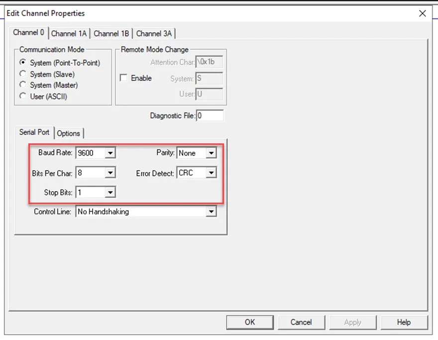
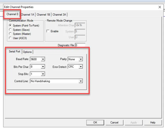
Note: When configuring the settings for the PLC, the Error Detect setting must be set to CRC, otherwise a connection with Litmus Edge won't be successful.
Refer to the following parameters and reference images when setting up the PLC.
- Device: PLC5/40C
- Communication I/Fꓽ RS232
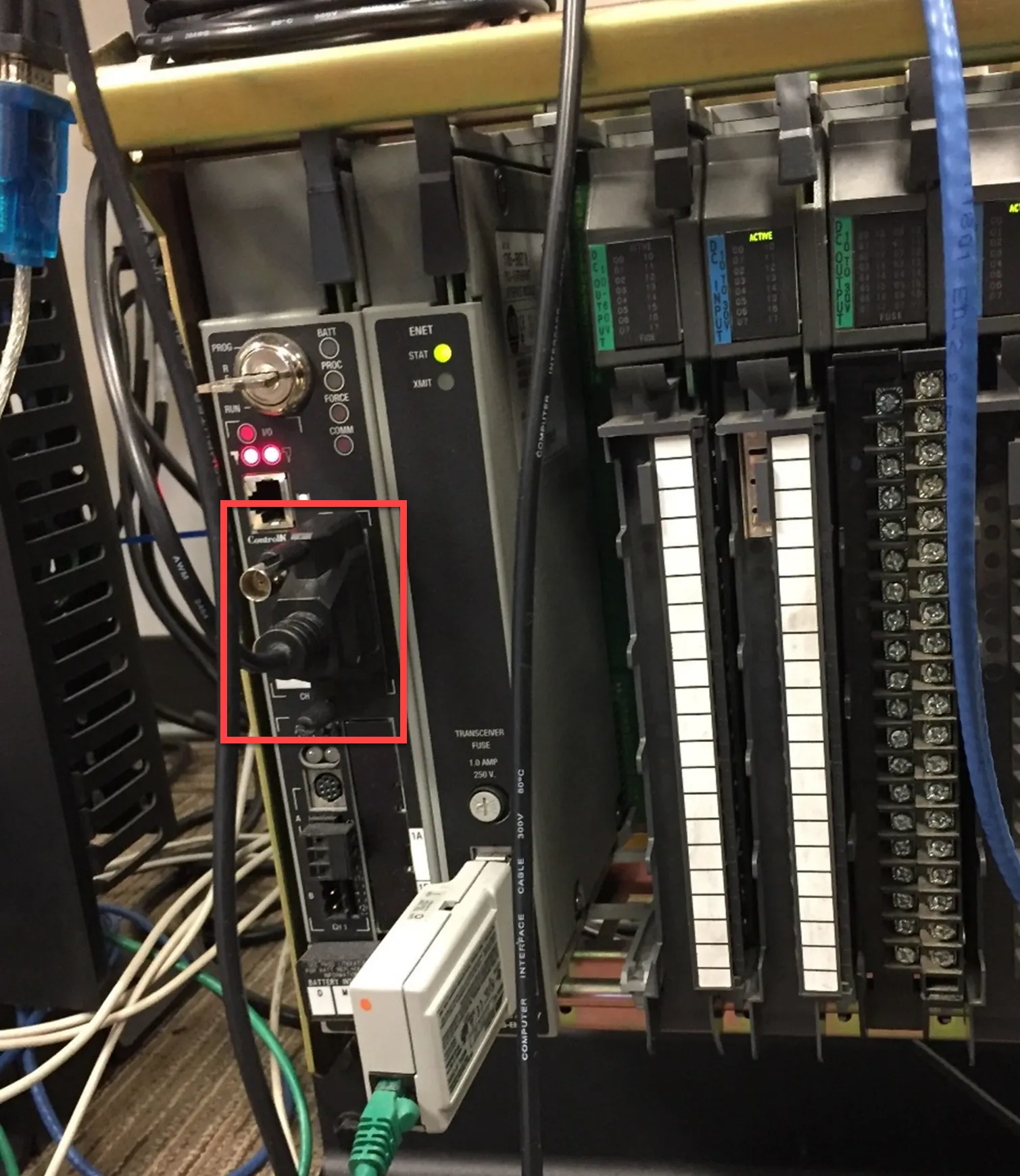
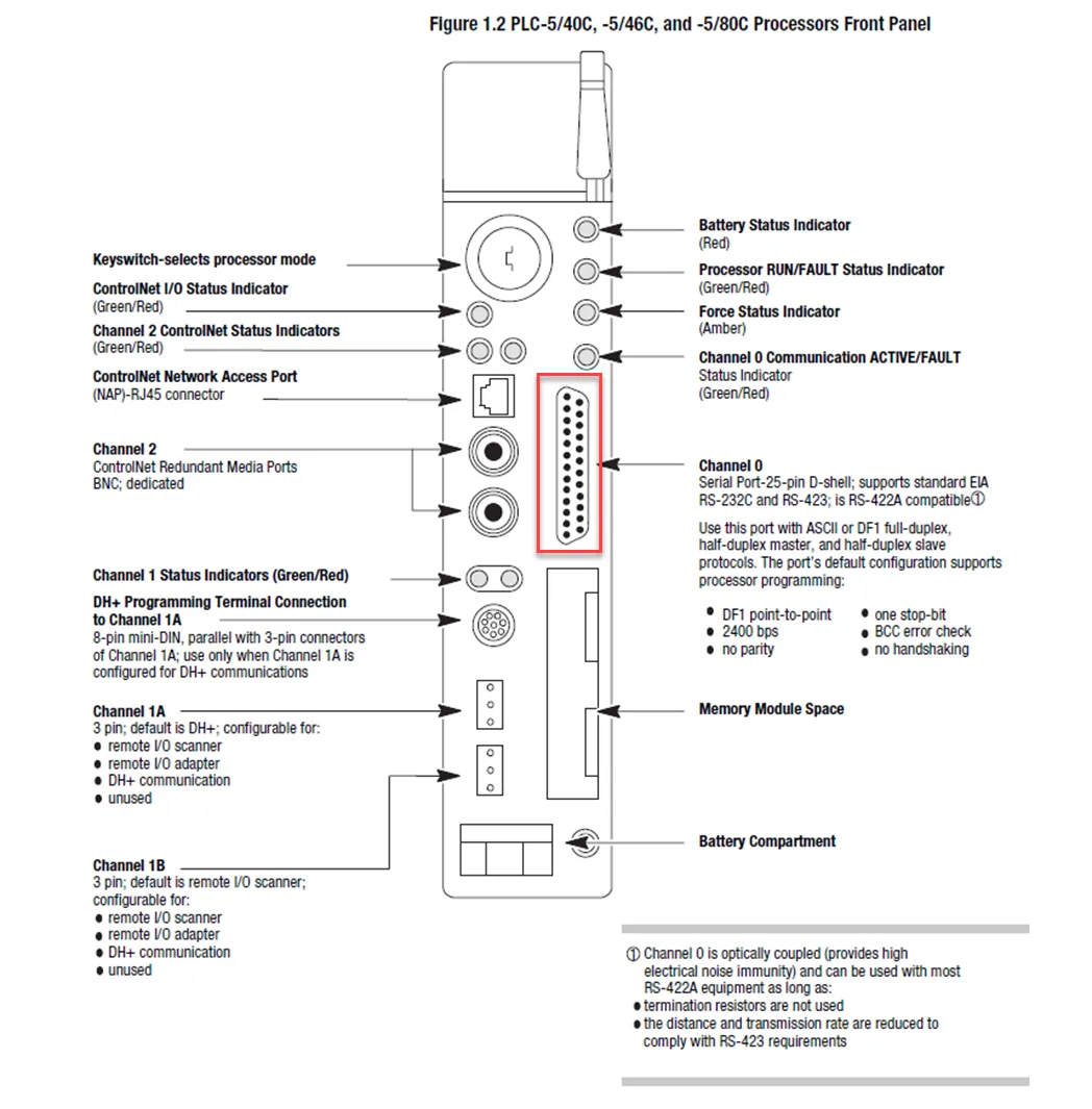
Complete the following steps to setup and configure the PLC.
To configure the PLC:
- Connect the PLC to the computer with a serial port 25-pin D-shell cable.
- Open RSLinx Classic software.
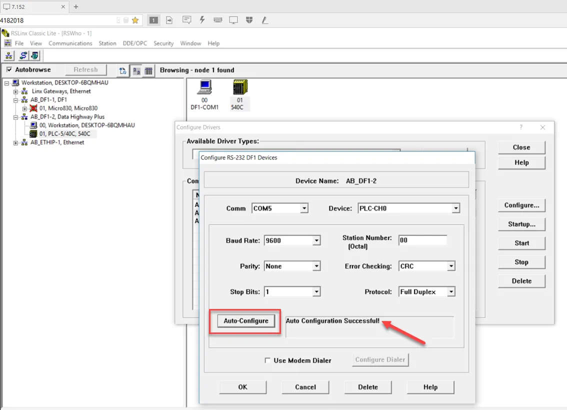
Click the Configure Drivers icon. Then, click Add New... and add the RS-232 DF1 devices driver.
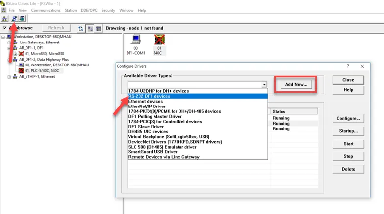
Configure the driver with the following parameter values and click OK. Baud Rate: 9600 Bits Per Char: 8 Stop Bits: 1 Parity: None Error Detect: CRC
In the driver settings, click Auto-Configure and confirm you see an Auto Configuration Successful! message.
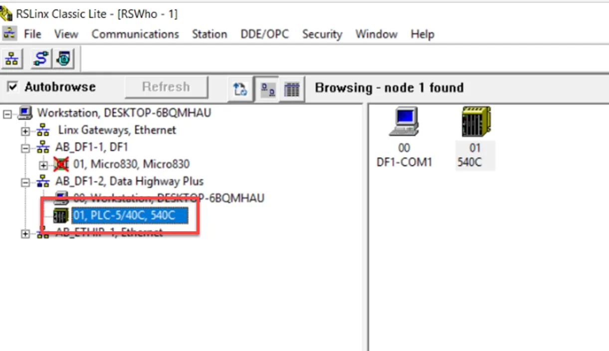
Ensure these same settings are configured in the PLC to establish a connection.
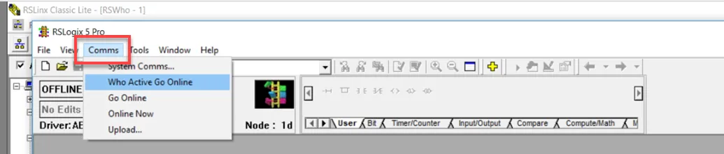
- Open RSLogix 5 software.
Click Comms and select Who Active Go Online.
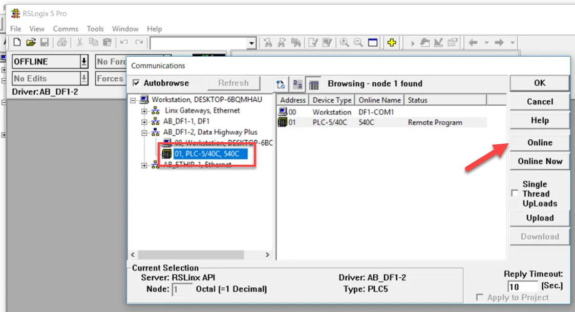
Select the device that you configured and click Online.
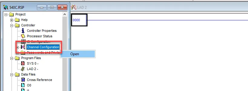
In the navigation menu, click Channel Configuration and select Open.
Confirm the Serial Port settings for Channel 0, which is the RS232 port. Note down the Baud Rate, Data Bits, Stop Bits, and Parity. The Error Detect setting must be set to CRC.
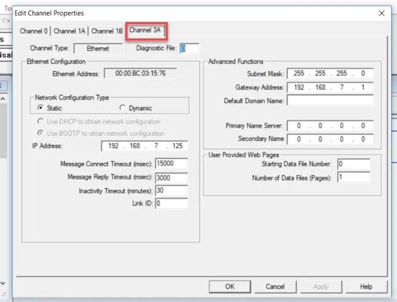
You can use Channel 3A to configure the Ethernet port, if applicable.
Step 2: Set up the PLC Device in Litmus Edge DeviceHub
Configure the following parameters when you Connect a DeviceConnect a Device with this driver. Update default values to the specific setup of your device.
Parameter | Value |
|---|---|
Type | Allen Bradley |
Driver | AB DF1 Serial |
Communication Port | Local Serial connection file path |
Data Bits | 5 6 7 8 |
Baud Rate | 1200 2400 4800 9600 19200 38400 57600 115200 230400 460800 921600 |
Parity | Even, Mark, None, Odd, Space |
Stop Bits | 1 1.5 2 |
PLC Type | PLC5 |
Source ID (SRC Byte) | 0 |
Destination ID (DST Byte) | 1 |
Read Timeout | 200 |
Retry Count | 2 |
Step 3: Configure the List of Registers
When you Add Tags to the connected device, refer to the following register table and tag parameters.
Refer to the following additional resources:
Register Table
cNote: The register table below represents the PLC address format. In Litmus Edge, you will need to enter the tag address in decimal format. This means you must convert the PLC addresses for the Input and Output Data Files from octal format to decimal format.
Name | Value Types | Access Types | Address Format | Min Address | Max Address | Description |
|---|---|---|---|---|---|---|
O | uint | R/W | OOO | 0 | 255 | Output |
O_bit | bit | R/W | OOOoo | 0 | 25515 | Output |
I | uint | R/W | OOO | 0 | 255 | Input |
I_bit | bit | R/W | OOOoo | 0 | 25515 | Input |
S | uint | R/W | DDD | 0 | 255 | Status |
S_bit | bit | R/W | DDDdd | 0 | 25515 | Status |
B | bit | R/W | DDDDDdd | 0 | 3276015 | Binary |
T_bit | bit | R/W | DDDDD | 0 | 32760 | Timer |
T | uint | R/W | DDDDD | 0 | 32760 | Timer |
C_bit | bit | R/W | DDDDD | 0 | 32760 | Counter |
C | uint | R/W | DDDDD | 0 | 32760 | Counter |
R_bit | bit | R/W | DDDDD | 0 | 32760 | Control |
R | uint | R/W | DDDDD | 0 | 32760 | Control |
N | uint, int | R/W | DDDDD | 0 | 32760 | Integer |
F | float | R/W | DDDDD | 0 | 32760 | Float |
D | bcd | R/W | DDDDD | 0 | 32760 | BCD |
A | string | R/W | DDDDD | 0 | 32760 | ASCII |
ST | string | R/W | DDDDD | 0 | 32760 | String |
Tag Parameters
- Name: Select a register name from the drop-down list. The available options depend on the names in the register table.
- Value Type: Select a data type from the drop-down list. The available options depend on the register name selected.
- Polling Interval: Enter a value in seconds. This determines how often the tag should poll the register for data.
- Tag Name: Enter a name for the tag.
- Description (Optional): Enter a description for the tag.
- Address: Enter a tag address. The value must in the decimal format, within the allowed min/max range. Omit the leading zeros. The device might use the decimal (D), hexadecimal (H), or octal (O) address format. See the Register Table at the bottom of the dialog box. For Bit tags, append the bit address without the bit separator. The lowercase letters in the address format indicate how many digits you should enter in the Bit address.
- Count: Enter the number of register values to read. A count higher than 1 will generate an array of values from the address value configured and respective subsequent address values.
- Length: Available for ASCII Data Files. Enter the number of characters for tag values.
- Tag Formula: Enter a formula for the tag to process the generated data. Two variables are permitted: value (current tag value) and timestamp (current tag UNIX time in milliseconds). The following math functions are available:
- sin
- cos
- sqrt
- tan
- power: power(x) performs the operation 10^x.
- log: log(x) is the natural logarithm (the logarithm is in base e).
- exp: exp(x) performs the operation e^x.
- Only Publish on Change of Value: Select the checkbox to customize NATS messages to be published only when the value parameter changes from a previous value to a new one. Change of Value only applies to boolean, numeric (such as int or float), and simple string data types. It does not apply to complex types, such as JSON or array. Poll-once topics will not be affected by Change of Value settings. These topics will still only see a single message.
- Meta Data: Metadata summarizes basic information about data. This feature allows you to define key-value pair data for the device output payload later on. It can then be used to find, use, and reuse particular instances of data.
Note: If you use special characters in meta data key names, the special characters are replaced with underscore characters in the payload. This can cause two key names to be combined into one. For example, configuring the key names a**b and a&&b will cause only one key name to be created (a__b).